CAD, CAM, CGI, oh my!

B.L.U.F. hh465: I didn't come to FreeCAD as a novice. I jumped in because I thought my experience in AutoDesk Inventor would just transfer over. It didn't. On the other hand, I'm very, very pleased with the results. This article is from your prompt. Thank you. Maybe the write-up below will help you get started, then start looking for YouTube videos about the thing you want to do. Some of it is just wrapping your mind around different ways of accomplishing the same tasks. (1400 words, lots of images, two videos)
I have been working in computer graphics since around 1976. My first introduction to "CGI" was in the show The Man From Atlantis. In the show, they had a fancy echo locator/sonar/radar system. You heard this wonderful sound, and then they showed you the visual results. Those visual results were a standard demo for the Apple II. My parents were amazed by the technology of the TV show. Next time I had an Apple II home, I showed them the demo. It took a bit away. While at University, I did a little more with computer graphics, but it was mostly just line drawing stuff. We had some Tektronix 4010s. The only reason these were of interest to me was that I recognized the graphics in Battlestar Galactica were generated using Tektronix displays. After University, I did work at BRL. I was introduced to my Mentor and to CAD. My Mentor ruined CGI for me because suddenly, I could see all the artifacts of CGI in movies and TV shows. What is CAD? CAD stands for Computer Aided Design. In its simplest form, it is a computer acting as a drafting table.
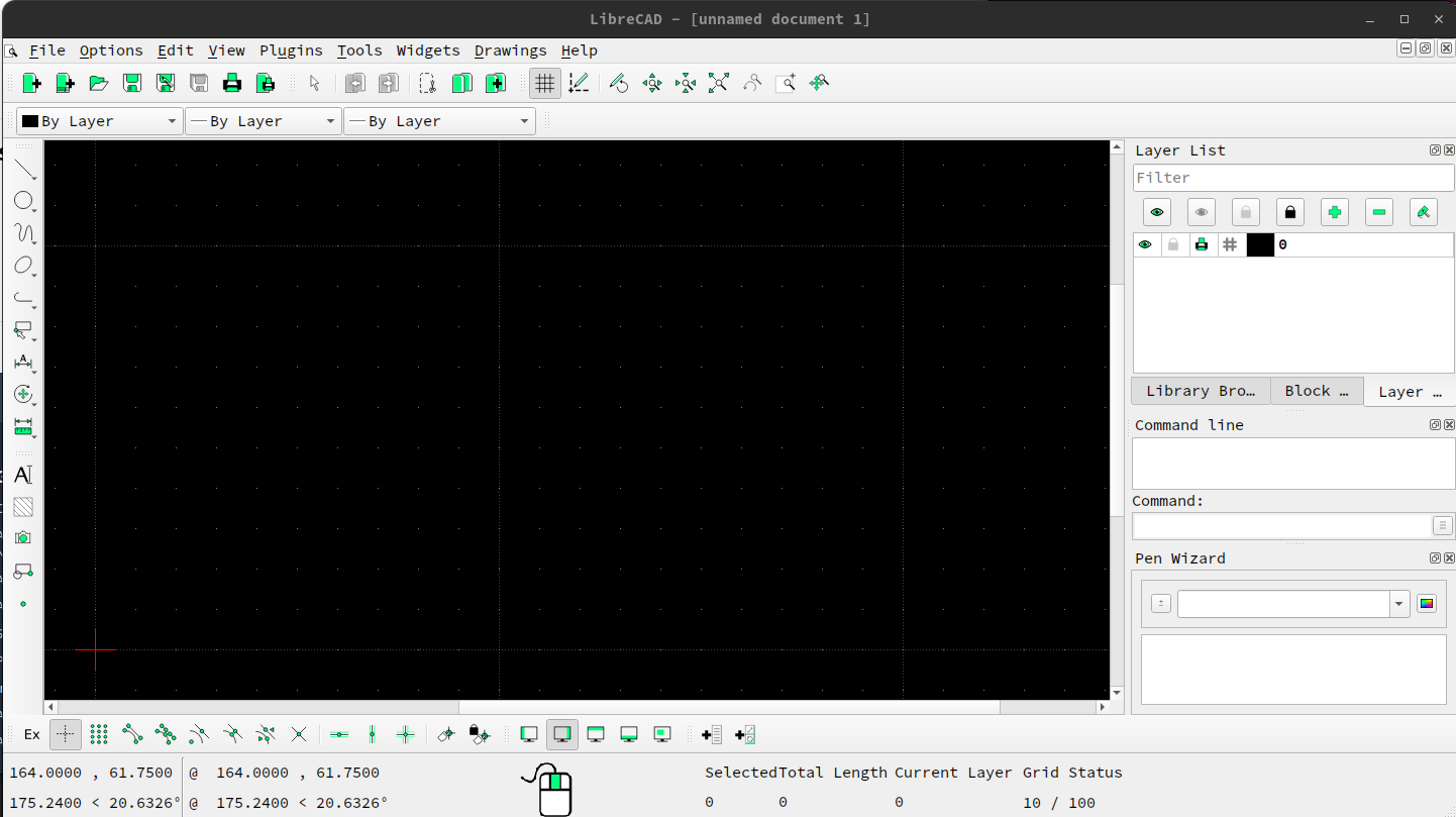
There are better, more expensive versions, this is an Open Source drafting program. If you look on the left-hand side, you can see the things you can draw. Those are just basic 2D lines and curves. The power of a system, such as this, is that it is easy to fix errors, it is easy to accurately draw lines and curves, and when you print it, it is easy to read. The commercial version of this program is AutoCAD which is not cheap. But that is the only thing it can do, print pretty drawings. Don't get me wrong, there are millions of things that exist today that were created from drawings constructed from these types of drawings. If we want to do anything more, we have to turn those lines and curves into a representation of a real-world object. So we describe an object in three dimensions.

What you see is still a drawing. It is a 2D drawing in the FreeCAD Sketcher workbench. But we see a couple of different things. We see there are four lines, but that those four lines are "constrained". We have constraints that make the sides perpendicular to the X axis and constraints that make the top and bottom parallel to the X axis. We also have constraints that say that the ends of the lines are connected. As long as those constraints are exist and are enabled, I cannot move the lines outside those constraints. The four constraints that make the edges parallel to the axis also mean that the lines have to have matching lengths. So we add a couple of more constraints. We are going to set the lengths of the lines.
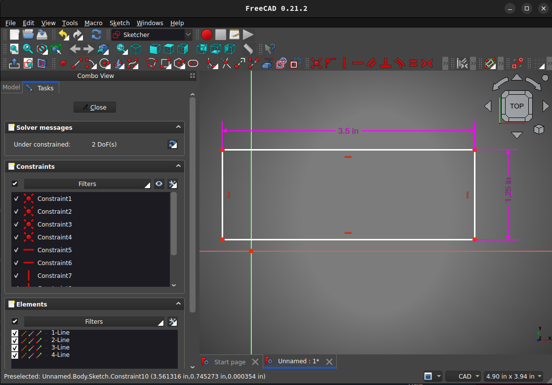
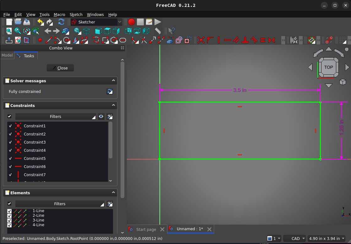
We still have a warning that the sketch is under constrained. It has two Degrees of Freedom (DoF). But now it is to size. We will add one more constraint to lock the lower-left corner to the origin. This will remove all the DoF and leave the sketch fully constrained.
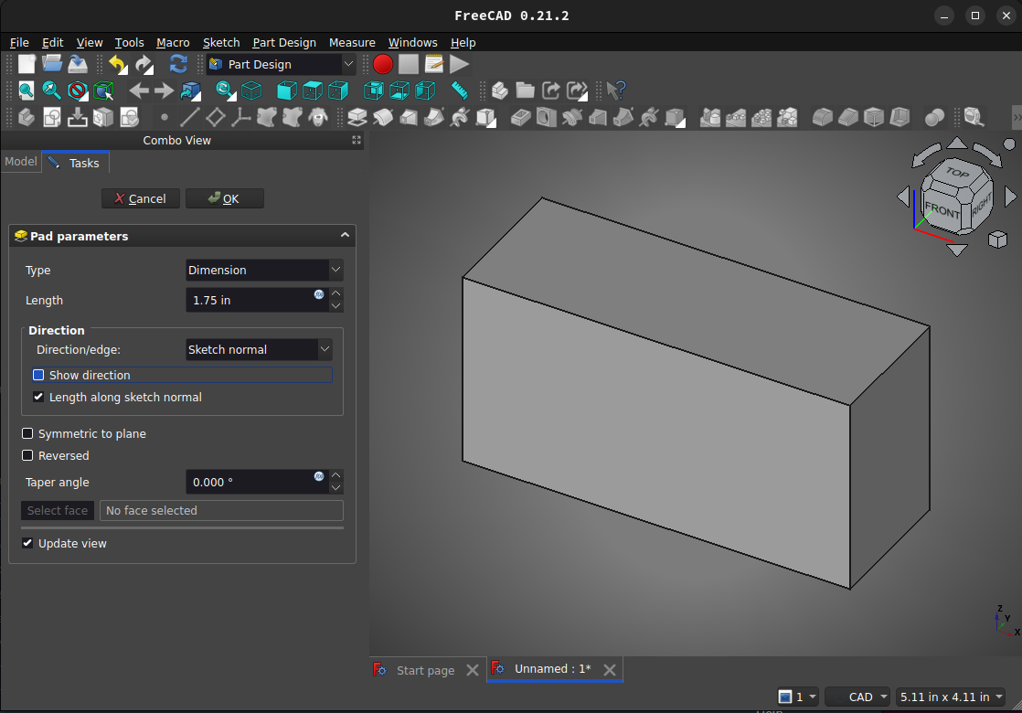
Now we will turn this into a 3D model. We will do this by padding the sketch to give it height. We will set the height to 1.75 inches.
We now have a thing that could be a block of metal, or a block of plastic. But it doesn't capture what I want. So I'm going to edit the sketch and create the 2D geometry to get the correct shape.

I now want to add some threaded holes and a slot. I do this by creating sketches on two faces.
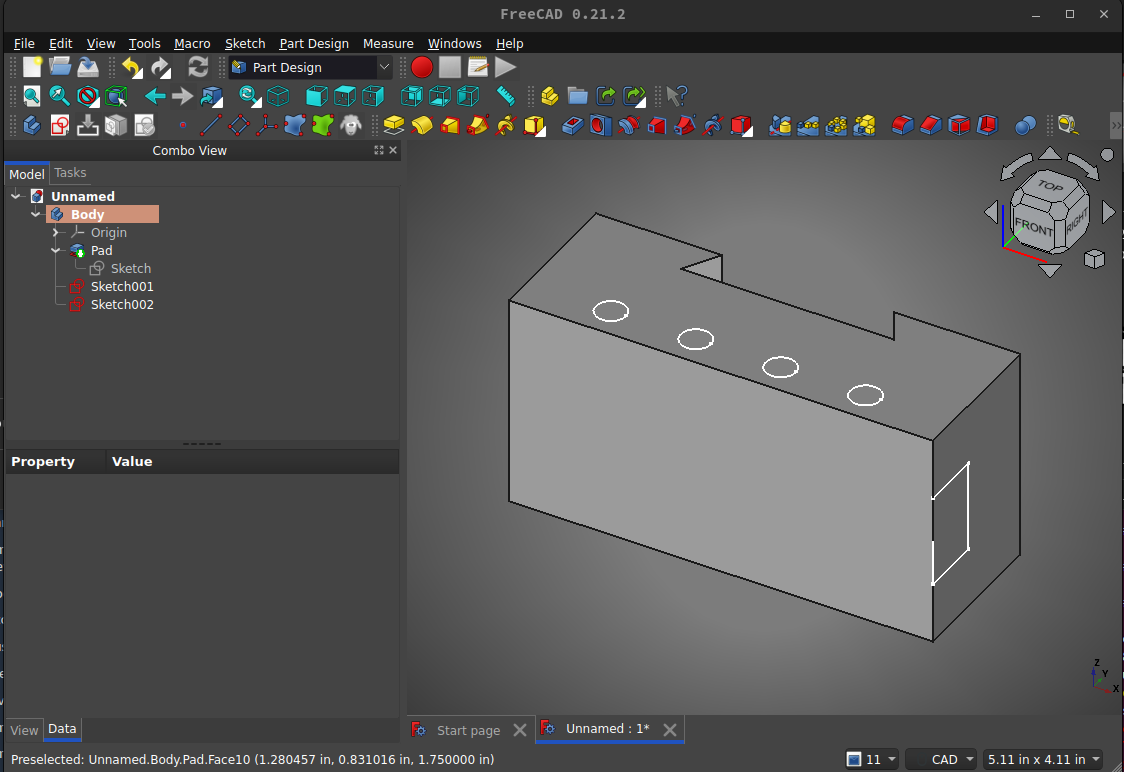
Now that I have the sketches drawn, I can subtract material. I will use the pocket tool to create a slot on the face. The sketch could have been drawn on the front face or the side face, as I did. By drawing on the side face, this allows me to add other features to the pocket, such as a V grove.

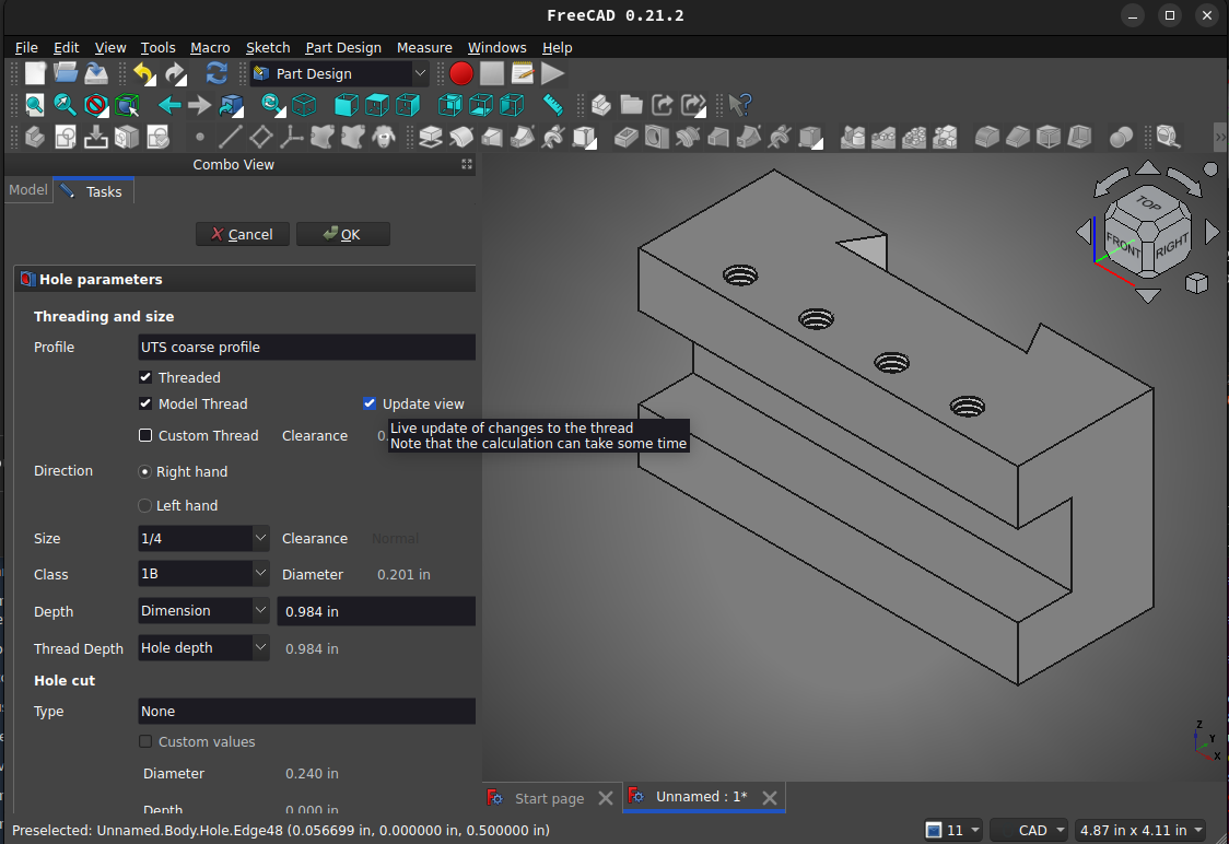
Now that we have the slot, we can add the holes. I will use the hole tool because it allows me to specify threads.
I now have a "part" that can be machined, but I can't look at this picture and tell what it is. I need a technical drawing, a blueprint.
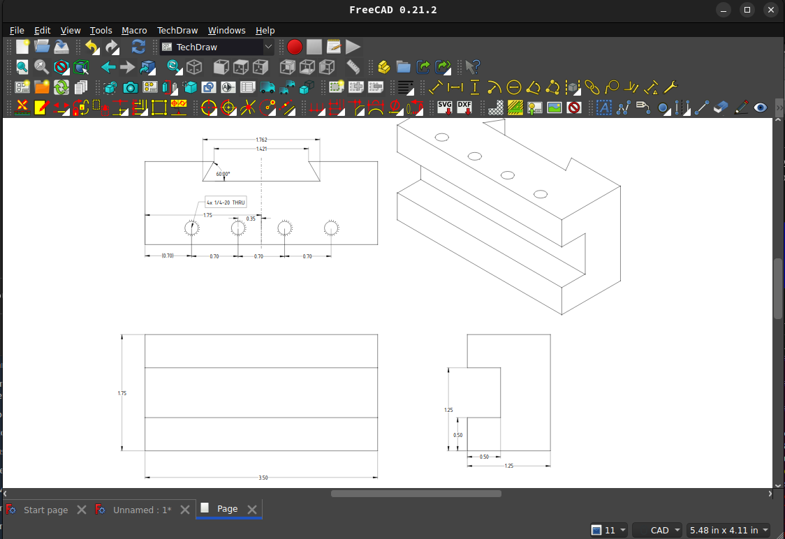
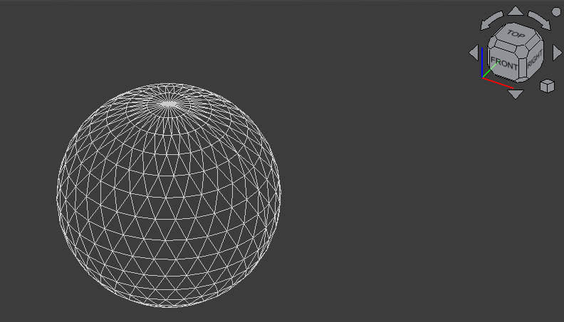
My drafting mentor might not be happy with this drawing, but I can machine this part from this drawing. Things that I left out because I was rushing, there is a relief cut into the dovetail center. I left off the chamfers. Regardless, this would be enough for me, and I hope a real machinist. The point to see, in all of this, is that everything is done to dimensions. The result is a solid. We can use FreeCAD to do different types of analysis on this solid, including Finite Element Analysis. We can even combine this part with other parts in an assembly. Once it is in an assembly, we can do interference tests, to see if it will all fit together. There are modules for FreeCAD that will turn that solid into an STL file which can be 3D printed. Unfortunately, there is an issue with this type of modeling, those circles are fake. For what I am doing, that does not make any difference at all. My final drawing, after all, is just a representation that can be machined. If I'm doing a FEM analysis, that breaks the solid into small elements and does the analysis on those small elements. A circle is made from a series of lines. The more lines, the more it looks like a round feature. Sometimes a model knows that something is a circle and adds more lines as you magnify it. But eventually, it turns into discrete lines. Consider the curved front glacis of a Sherman tank. If we want to know what happens when a projectile hits that surface, we need to know what the angle is. The angle changes for every point on the curved surface. If the surface is represented by facets, we are not going to have the correct angles. Using Combinatorial Solid Geometry, we represent objects/bodies by combining different types of solids. Thus, a sphere, which is represented by the location of different facets in surface modeling, is represented by a radius and center in solid geometry. I learned to model with CSG. I'm not good. The people I worked with were the absolute best in the world at it. Yes, I've seen CSG models of complex vehicles and it was very detailed. Using CSG and allows a different type of analysis that might not be possible with facets. FreeCAD uses facets for display purposes. It is the fastest way to do it. Each of the facets contains color information, and then a "shader" is applied. That shader can fake the color so that surface look curved, even if they are actually flat.

CGI has entirely different goals. Its primary goal is to make something look real enough. [videopack id="93363"]https://GunFreeZone.net/wp-content/uploads/2024/01/animation-test.mp4[/videopack]
This was a test in Blender. Everything you see is simulated. The movement of the clothing is done via a physics simulation. The way the woman moves is a combination of motion capture with added physics. When everything is said, in that movie, nothing can be actually measured. No matter how real it might look. Blender can do things that CAD programs cannot do. [videopack id="93365"]https://GunFreeZone.net/wp-content/uploads/2024/01/Sonic-w-blur.mp4[/videopack]
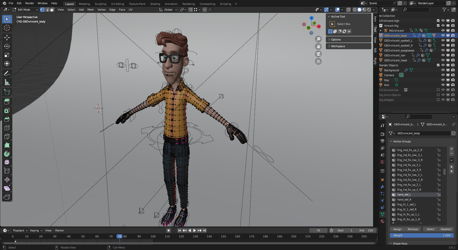
And here is the Blender interface. I will admit that it's been a bit since I used Blender. I can't remember anything about how to use it. Just getting this one image took longer than I wanted.